Tuesday 7 October 2008

Tutorial: Texturing and Lighting


Texturing
Today we had a tutorial in texturing and lighting using the Lego man from the previous tutorial.
The tutorial consisted of:

-How to create a material from scratch with the basic usage of each of the material properties in the material editor (colour, diffuse, reflection, bump, etc).

-Using images within each property in the material editor.
Using images to affect the various properties. Examples were given on how to take a texture such as an image of a scratched surface and using within the bump channel to make the surface 'bump'out as in the image, or using it as a reflection map so the material will reflect that image as though it is part of the enviroment. Examples were given for each channel(property) within the material editor.

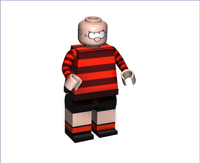
-Creating the face on the lego mans head.
using an image created in photoshop to map into the colour channel of the material for the head. We were shown how to position the image/texture so it appears correctly on the model.

The exercise was repeated to create an image on the torso. An example was given where the texture can be applied to only one polygon.

I decided to make a lego 'dennis the menace' and created the following textures in photoshop. The face is copied from my reference image.


The following Image shows how the 'face' texture is applied into the colour properties of a material. It also shows which properties i have turned on for my lego material. Color, reflection and specular are used.


The following image shows the material applied to the head, and the settings that are adjusted to fit the image to the model correctly. cylindrical mapping gave the best fit for the head.


I applied the other textures in the same way. The body worked best with cubic mapping and the arms were best left with the default uvw mapping.


3Point Lighting

The next part of the lesson was a tutorial in 3 point lighting. 3 point lighting is good for realistically lighting an object, without drastically increasing render times. Better looking methods of lighting are available although these can cause much longer rendering times.

The tutor created his 3 point lighting setup that consisted of:

Backlight-An area light placed behind the object being lit, to simulate 'bounced' light.

Arealight-Another area light scaled quite large and positioned directly above the object to be lit. The brightness is lowered on this light to create the right effect.

Main light-Placed in front of the object in the same direction as the camera. The tutor had turned on shadows for this light only.

Image shows the result of the tutorial.

I played around with this setup and found that the scene looked much better with the ground plane being excluded from illumination by the backlight and area light.

The Image below shows results after changing the brightness of each light and repositioning them slightly. only the main light affects the floor. While all 3 lights affect the character.

useless post

(irritating bugs in this blogger. I have to continue in the next post. Im not sure how to delete this one?)

Mini Project - Pingu - modelling the characters

I set myself a mini project to recreate a scene from the animated series, 'Pingu', using concepts learnt in class. I'll add to/ change things in this scene as I gain more knowledge.

PINGU

Step 1: Set up reference images in the viewports.

The image below shows the background images I have assigned front and right viewports. I have turned the brightness of these images down (to 'fade' them) as I find it easier to see my wireframes on top.

Step 2: model a 'wing'.

I started by creating and resizing a cube to the rough dimensions of the wing, and moving it to the correct position. I then adjusted amount of segments along the legth to 5 (i wanted a low polygon count to avoid long render times later) and turned on 'fillet' in the cube properties to lose the sharp edges. I made the object editable, then repositioned vertices according to my reference images. The image below shows how my wing is positioned to the reference images.

step1 + step2.

Step3: apply a hypernurbs object
i applied a hypernurbs to the wing to see how it will look when 'smoothed'.

step3


Step 4: Model the body

The first step was to create a sphere and adjust the vertices to create the shape of the white 'inner' part of the body. This is a kind of egg shape.
To create the black 'outer' part of the body, I duplicated the 'inner body' and hid the original. I then selected the polygons that were in the area of the 'outer body', inverted the selection and deleted the uneeded polygons. I reposition the edge vertices to get a smoother shape to the edges. The outer body was given thickness by selecting all the polygons and extruding outwards.

Step 5: model the head

the head, eyes, pupils and beak are all spheres that have been scaled along the relevent axis (x,y and z) and moved to the rough positions in the reference images.

step 4 + step 5


Step 6: Model the feet


The feet are cubes with 3 depth and width segments, with the vertices positioned to the rough shape and size of the reference images.


The low-polygon model

I unhide all my parts when they are all modelled. The following image shows the low poly model without hypernurbs objects applied.


With hypernurbs applied

The hypernurbs is applied to all objects except the eyes and pupils


SEAL

I found an image of a still from an episode of Pingu. it shows some of the enviroment, Pingu and a seal. I dont know if the seal has a name so ill just call him 'seal'. I decide to create 'seal'. I used the following image as a reference.


Image from http://www.pingu.net/uk/


Seal Step 1: Body
I created a cube and positioned it to the neck/shoulder area using my reference image as a guide, i then extruded the bottom polygon downwards and repositioned/resized the extruded polygon to the right position for the next extrusion. I then repeated this process until i reached the tip of the tail. The tail fins were extruded from the sides of the tail.

Seal Step 2: Head
The head is simply a squashed sphere with the mouthparts created with 2 extrusions and repositioning/resizing of the polygons.

step 1 + 2


Seal Step 3: apply hypernurbs and readjust low poly model.
A very useful feature of the hypernurbs object is that you can work on a low polygon model whilst seeing the results with a high level mesh. In other words, i can work on the mesh in the image above while seeing the results as in the image below.

Step 3 seal step 4:

I merged this object with my 'pingu' model and copied the flippers from pingu, and repositioned/resized the copies to fit 'seal'. A small sphere was added to create the nose and the eyes were copied from my 'pingu' model.

step 6

Wednesday 1 October 2008

Creating a Lego Man

We followed a tutorial in class on creating a lego man in cinema4D.
The tutorial showed how to:

Set up reference images in the viewports. Browse to an image for the background of the viewport.

Create the body.
Create the 'body' by reshaping a cube to the right dimensions.
Make the body thinner towards the top by scaling down a group of vertices.

Create the waist.
Change the dimensions of a cube to the right size.
Use a cylinder to cut away part of the waist, creating the leg 'sockets'. (using the boole tool)
Use a cylinder to create the groin area piece.

Create the legs by resizing a cylinder for the 'hip' and connecting a resized cube for the leg.
creating the foot by extruding polygons from the leg.

Create an arm using 'Sweep nurbs' to 'sweep' a closed spline (circle) along a spline (line drawn with bezier tool) This would be useful for things like a hosepipe or tentacles.

Create a hand by using a cube to cut away a piece of a tube using the boole tool.

Create the head by creating a cylinder and using the 'fillet' tickbox and values to 'round off' the edges. The small noddle on the head is extruded polygons.


In the above image, I have created and applied 4 materials and adjusted the various values in the specular settings of each material to give a 'lego plastic' look.

I have also placed 3 lights in the scene, 1 of which has soft shadows.

You can see that the legs and waist have very sharp corners and edges, and the body has subtly rounded corners, as this is the case with the actual lego pieces.
This was done (after gleaning advice from my tutor) by using the knife tool to 'cut' through the body close to each edge (except the bottom edge). A hypernurbs object is then applied to the mesh that rounds off the edges. (applying hypernurbs without the cuts would have resulted in a blob like object)